SCADA
SCADA system implementation
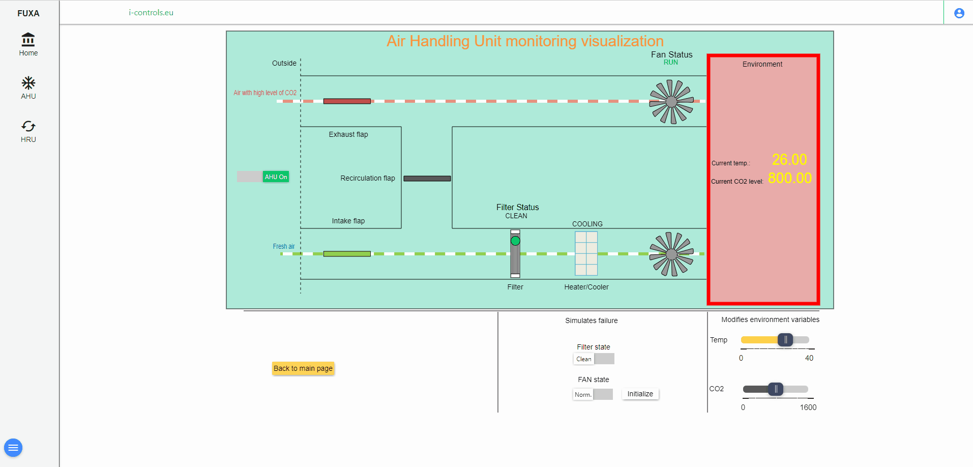
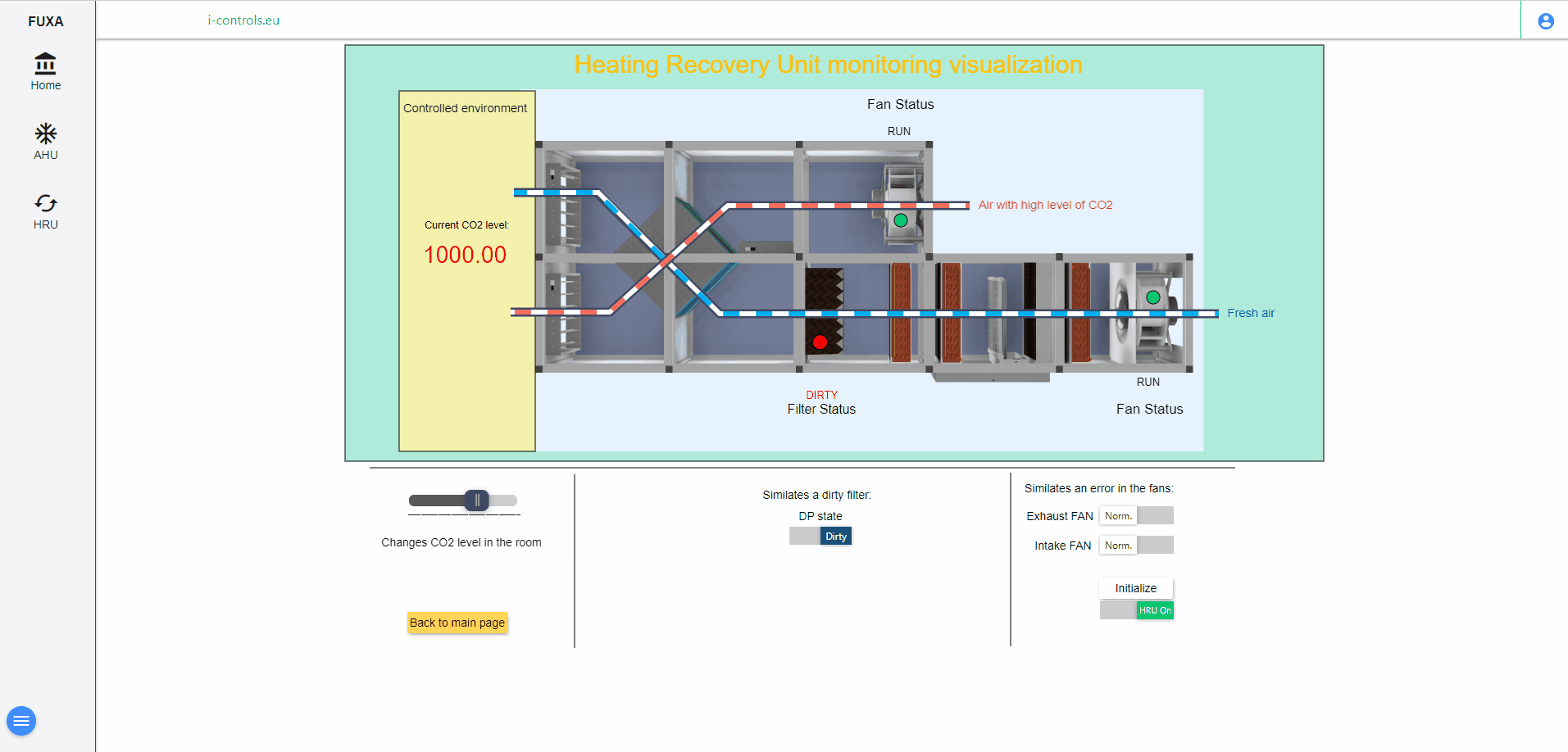
SCADA (Supervisory Control and Data Acquisition) systems are widely used to monitor and control critical processes in manufacturing, power generation, and transportation industries. A SCADA system is typically made up of hardware and software components that work together to collect and analyze data from sensors, control devices, and other sources to provide operators with real-time information about the status of the process under observation. SCADA implementation can be a complex and difficult task that requires careful planning, design, and configuration of system components and considerations for communication protocols and security measures. In this article, we’ll look at the key aspects of SCADA implementation, from system design basics to best practices and case studies, as well as future trends in the field.
Innovation Controls Ltd. develops various types of devices at the request of the client and offers services such as product design and integration of the SCADA system in various production processes. Thanks to the MODBUS protocol, various process sensors can be monitored.
FSC-1
Controller for contact systems with embedded wiring monitoring function
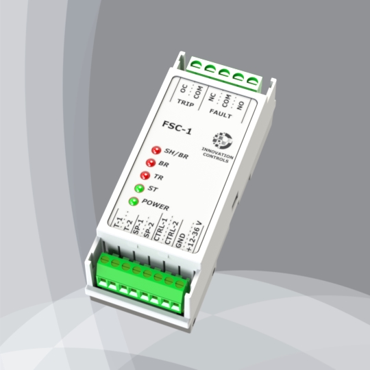
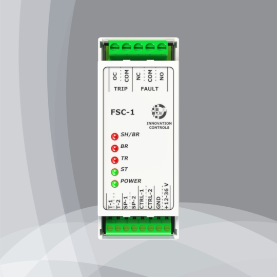
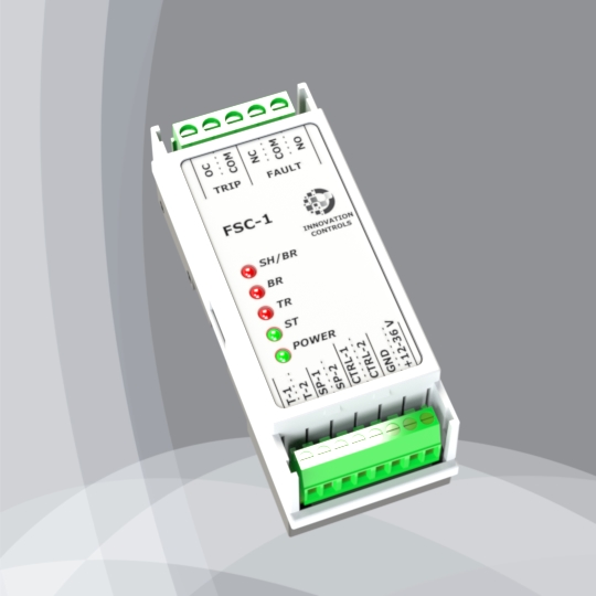
FSC-1 is a compact electronic module designed to monitor the state of the contacts of responsible sensors or actuators. It has been designed with 2 relay outputs: the first one switches depending on the state of the sensor’s contacts (open/closed), and the other switches depending on the state of the connection line/wires (break or short circuit) to the sensor. There is an additional input for monitoring the status of the sensor connection line and the ability to turn off this line and simulation of the sensor’s normal operation. This mode is necessary during checking or repairing the sensor connection line without having it disconnected from the controller and stopping the operation of the entire system. For easier verification, in this mode, additional outputs are provided to which the sensor connection line connects. Its design allows easy mounting on a DIN rail.
Power supply: 12 – 36 VDC;
Sensor inputs (SP1 – SP2): a resistive divider is required, mounted on the sensor contacts according to the diagram attached below;
Control input (CTRL-1 – CTRL-2): contact input (relay, transistor): switches the sensor connection line to be monitored by the controller or simulates the normal operation of the line;
Outputs (T-1 – T-2): the sensor connection line is being switched to these outputs during the mode of normal line operation simulation is
engaged. In this mode the Control input (CTRL-1 – CTRL-2) is OPEN;Relay output “TRIP”: 230V / 5A AC3 contact. It monitors the state of the sensor contacts. When they are closed, this relay output is switched;
Relay output “FAULT”: 230V / 5A AC3 contact. It monitors the condition of the sensor connection line /wires to the sensor. In case of open or short circuit, this relay output is switched;
Max operational temperature: 70C;
Humidity: 0.95%rh;
Degree of Protection: IP20;
Housing: ABS plastics.
- Datasheet: DS-FSC-1.pdf
- Ordering info: FSC-1